ESC : Real PCB, Technical Aspects & Personal Thoughts
Useful Links
Introduction & Context
During the past few months, I’ve been working on my power electronics skills through a project that felt easy on paper, but turned out to be a bit more complicated than expected. This project is the HOLY ESC; ESC standing for “Electronic Speed Controller”.
The goal of an ESC is simple: grab DC voltage from a battery, and somehow make a 3-phase BLDC motor spin from that DC current. This goal is simple but can be achieved in many ways, each solution involving specific electronics, software and silicon requirements. My solution explore the BEMF method to control the BLDC motor, final application being for a fully custom drone.
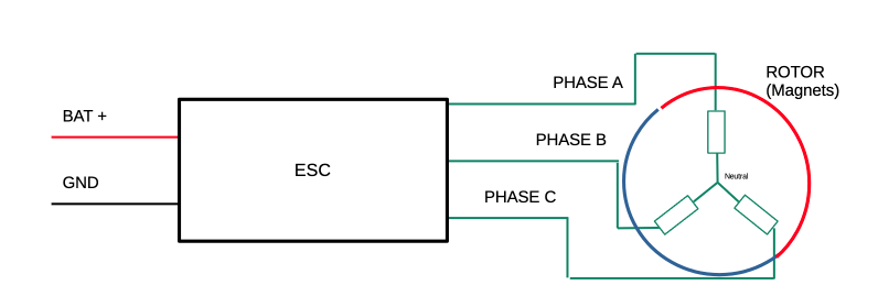
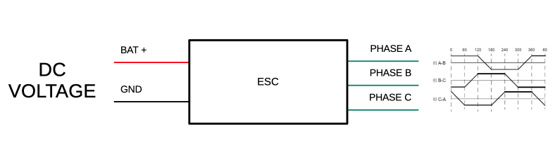
Note I already have a 1st post on the subject : 1st ESC post
What’s New ?
Okay so in the last post we left on the fact that the PCBs were designed.
This post is going to be a light one as pretty much every struggle aspect of the project is documented in this YouTube video:
Yet, here, I’ll discuss some more advance technical details that I didn’t have a chance to talk about in the video, like:
- How I handled BEMF noise on a perfboard.
- What does the last ESC revision bring.
- Theorical maximum current.
As well as some personal thoughts and learning from this project:
- What I learned
- How I feel about the project
- How I feel about the youtube video
Technical stuff
Perfboard, Noise, Trick and System Reponse Analysis
First of all, the NOISE !
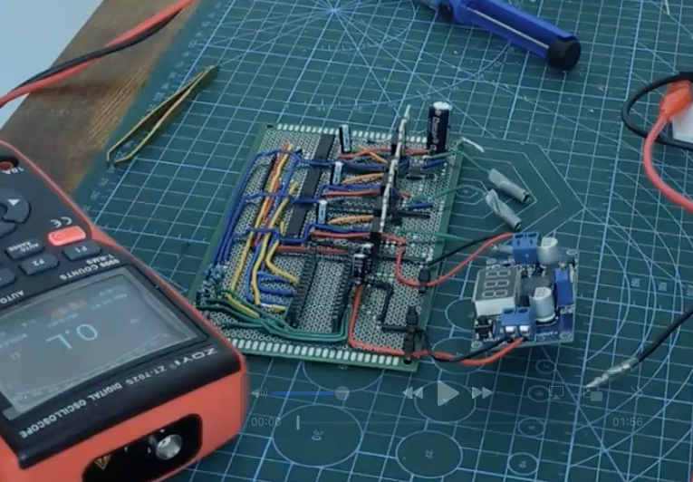
Perfboard prototypes are super bad for a loads of reasons:
- Ground is extremely bad everywhere.
- No ground plane
- Cables pickup all the noise
- Etc..
So the backemf signals were super noisy which cwas triggering commutation at random moments.
Here is the noise due to ripple for example (I had multiple 470uF caps on that rail !! plus 100nF at the pins !):
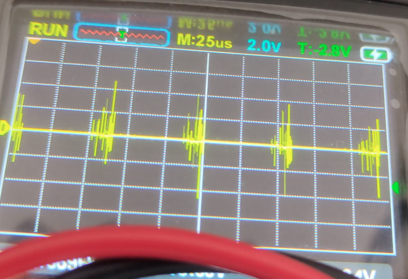
And the Back emf signal itself:
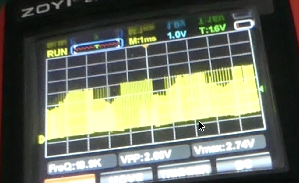
Franckly it does look like regular BEMF signals under PWM duty, but zoomes in, the ripple makes it vey unconsistent, couple with bad ground everwhere, I had to resort to blanking read tricks and software filters to get a somewhat ok reading of this.
I slao tried to filter using an RC circuit:
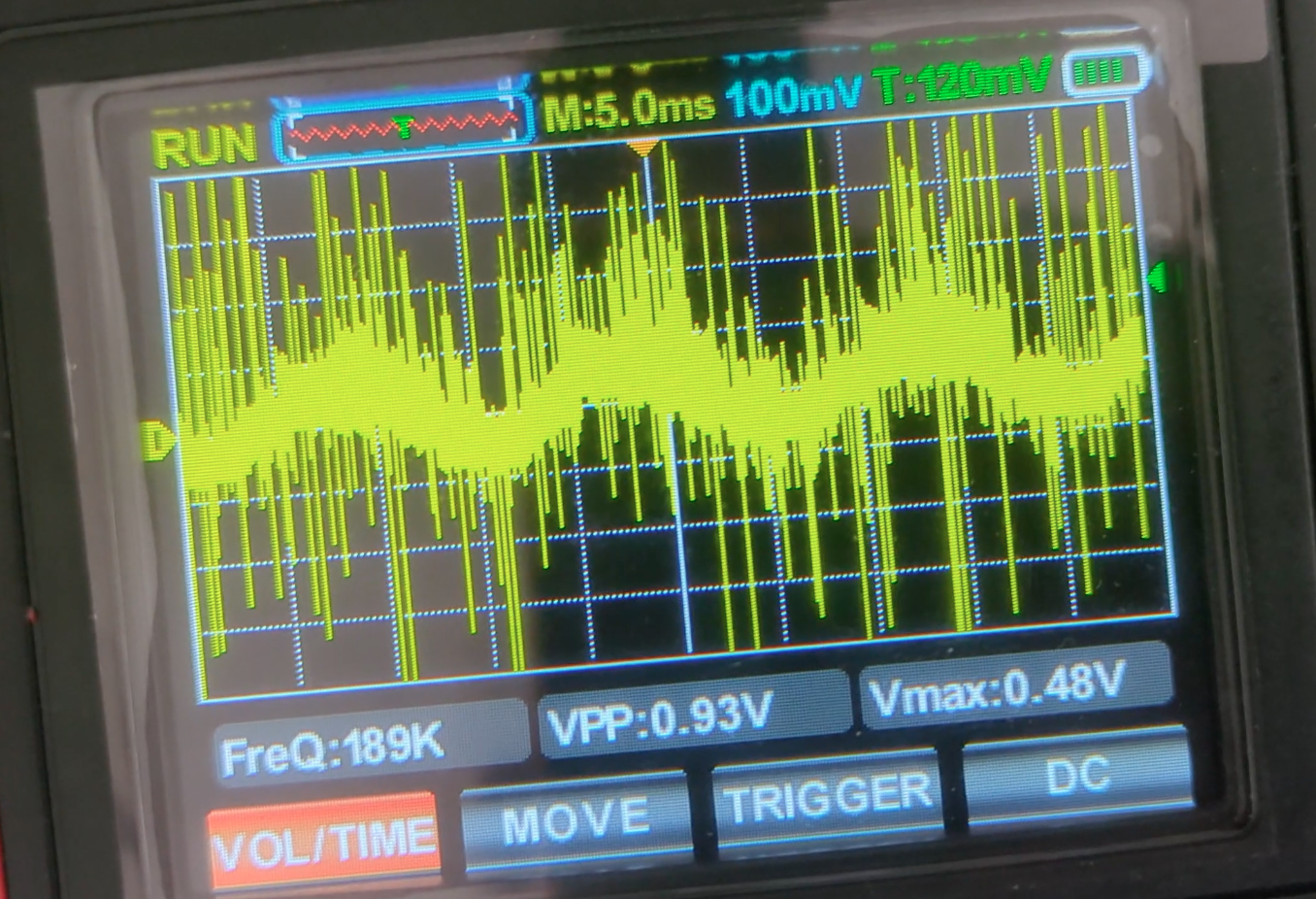
but yeah, not matter the RC value I used, the signals didn’t make sense anymore and is was son noisy that it was basically unusable, prbably de to the fact that precise RC filtering was not a good idea on such a noisy, compact and badly grounded perfboard prototype haha.
Anyway, back to the BEMF signals raw. To read them I used
- blanking perdiod (to avoid reading right after PWM switching which induced lots of transient noise)
- basic mooving average filters so that bad commutation (early detection due to noise) gets damped and the motor does get hardstuck instantly.
Stangely enough, a simple 2 sample mooving average filter did the trick, and tha motor was able to spin closed loop !!
here is a code snippet to see how simple the code was:
1
2
3
4
5
6
7
8
9
10
11
12
13
14
15
16
17
18
19
20
21
22
23
24
25
26
27
28
29
30
31
32
33
34
// Closed loop logic : we sample ADC to check BEMF value againt ZC THRESHOLD.
// A Blanking period is used to avoid sampling on rippled signal.
// Note the Arduino is too slow for that.
// The motor struggles to go fast / push the throttle.

bemf_t_0 = ADCH;

if (do_comm_once == 0 && blank_count >= BLANK_TICKS){
switch(step){
    case 0: case 1: case 2:
    if(bemf_t_0 < THRESHOLD_ZC){   // We crossed 0, we reset timer 1,
        TIMSK1 |= (1 << OCIE1A);     // re-enable, fires once after 30°
        raw_period = TCNT1;         // Get new last Period from last switch
        last_period = (raw_period + last_period) >> 1;
        zc_count++;
        do_comm_once = 1;
        OCR1A  = last_period >> 1;   // set delay = 30e° from the last period ‡/ 2
        TCNT1 = 0;
    }
    break;

    case 3: case 4: case 5:
    if(bemf_t_0 > THRESHOLD_ZC){
        TIMSK1 |= (1 << OCIE1A);
        raw_period = TCNT1;         // Get new last Period from last switch
        last_period = (raw_period + last_period) >> 1;
        zc_count++;
        do_comm_once = 1;
        OCR1A  = last_period >> 1;
        TCNT1 = 0;
    }
    break;
}
}
But the thing was the motor was super limited by that logic. Because the more samples use used for the moving average, the narrower the low pass property gets. i.e. the acceleration was way worse and the motor may not adapt as well to speed oscillations dur to torque ripple or the load, whicn caused instability on an unloaded BLDC motor that has high frequency speed variations. So it was a big tradeoff between eliminating mis interpreted zero crosses on the BEMF and phase response of the system, thus the 2 samples mooving average being a “good enough” compromise.
To be honnest, adding a load may have added a real physical low pass, which would have made testing way easier, but I had no propeler on hand. So might as well stay in “hard mode”.
RApart from that filtering hack, the blanking period : these were the real bad guys. My Mosfet were NOT fast, they had a HUGE gate charge and bad propeties that made them not suited for HF PWM. The transient (linear) phase that I needed to wait out induced big dead times and big blanking periods. In the end, the real BEMF useful signal could only be read at a certain max frequency limited by that blaking period and the CPU speed on the actual useful time were I was not waiting for my interrupts to be somewhat valid. Ultimatly, this led to a slow max speed. My estimation were around the low 7 to 10 000 RPM which is okay if the propeler is huge for a fianl application, but let’s be honnest, it was just too shaky to be relied on at any point.
PCB design
Okay so at this point, I had to move to a PCB design.
This would get rid of most of my noise problem if I managed to route it right.
As well as the “transient” issues caused bad the shitty automotive application mosfets.
On paper, this would allow me to really devellop better performances as these were my 2 real and only big limiting issues.
But still, I decided to drop arduino and custom firmware support. At this point, I felt like I learned enough about these things that I felt confortable using an external firware (AM32) paired with a faster MCU.
Most of the reason being that, if a problem occured on the PCB, the last thing I wanted was to spend weeks debugging to know whether the problem came from my own firware or the hardware.
Anyways, I finally got the PCB done after considering all the issues above and making that final software side decision:
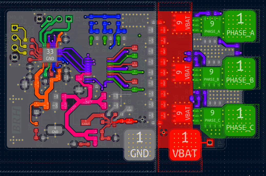
The design is somwhat the same as on a perfboard, except routing was a bit more thoughtfull (to lower noise and actually handle current) and the brain is now an STM32F051 to run AM32.
I also used way better FETs that were actually cheap + made for these types of applications.
You can see all the files and PCB details on the github : Link.
I then got them from PCBWAY which sponsored the youtube project:
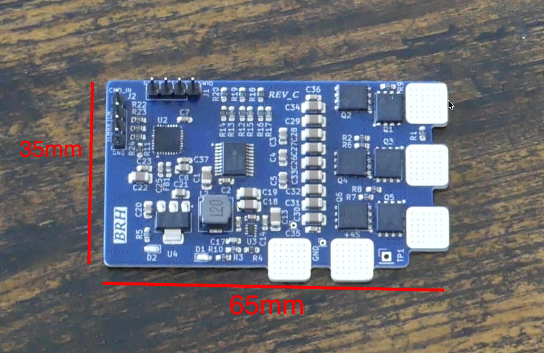
The PCB is 4 layers.
Total cost was 172$. First runs were closer to 350 $ but these used super expensive FETs.
I could get the costs down more:
- 22uF ceramic caps are 30cents + each, which gets expensive fast (could have used 25V-35V rated one which are 2-3x cheaper)
- BEMF divider was 0.1% tolereance due to me being paranoïd about that, but it was in fact not that important and I could have used standard 1% ones
- These is a back side silkscreen which is completely optional (but was better for the video)
- The specific STM32 MCU I use just gets bought all the time, could have used a cheaper one, this one goes for 5$ a unit on LCSC, which is inda expensive IMO when you can get similar MCU for 2-3$ max or even -1.5$ in bulk orders.
- There is thourhg hole components, and because I ordered the PCBA (fully assemble) this adds manual soldering which is not very smart whan I could easily have done this myself.
But I decided to gor for it anyways as the build was now whithin the sponsorship budget and the additionals designing hours were not worth the save for such a small batch IMO.
Theorical max current
Regarding the theoricall max current, The main limiting factors are the FETs internal resistance an my traces.
let’s first check the FETs internal resistance.
Thesez are HY904C2 mosfets which I get for 0;26 $ a piece a units worst case on LCSC:
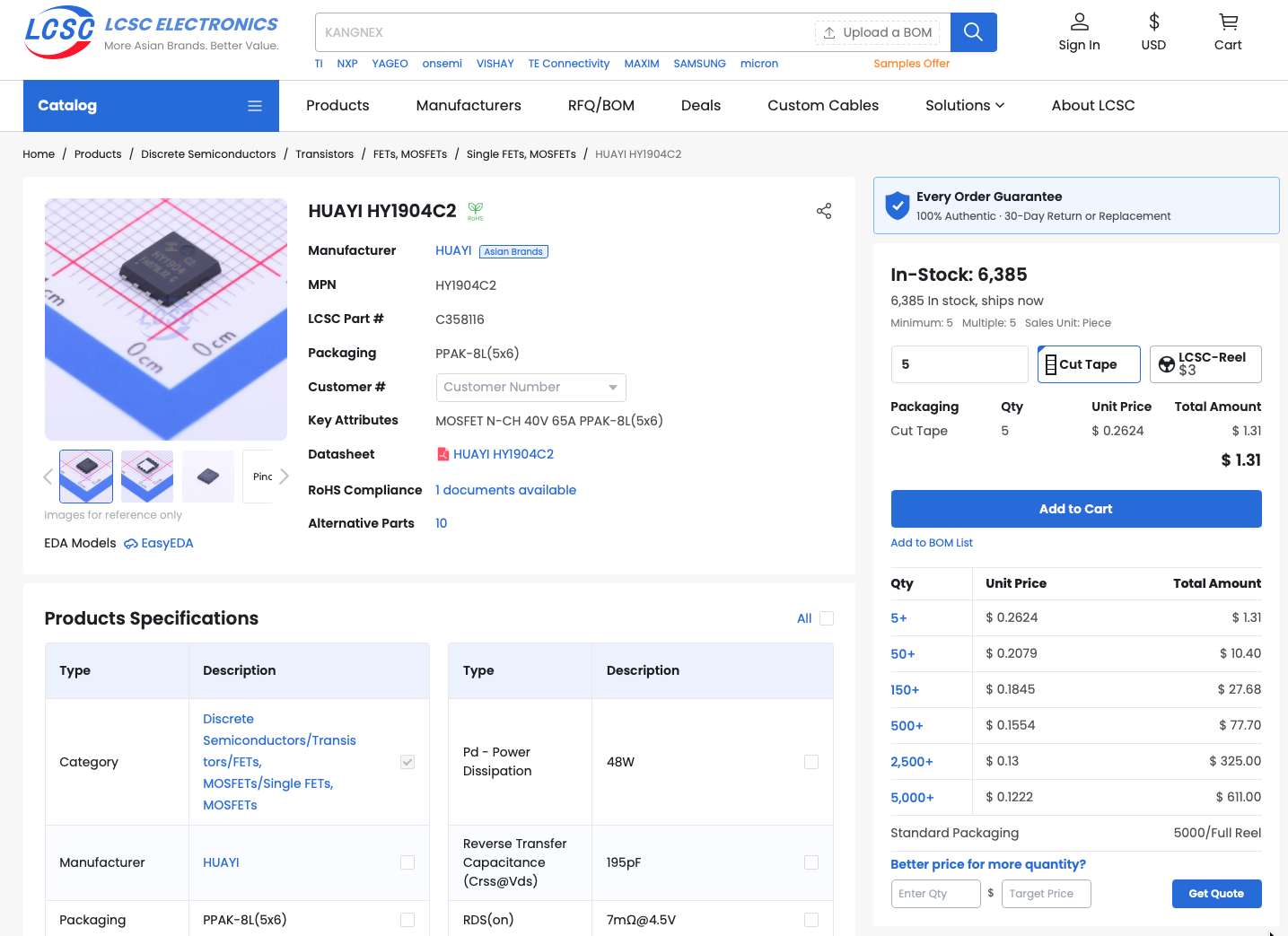
Which is a pretty goo deal ngl !
The fets have extremly low $R_{dson}$ and I drive them slightly above their rated typical $V_{gs}$ (@12V staying withing 20V max limit), making them super conductive, but let’s assume a 10V $V_{gs}$:
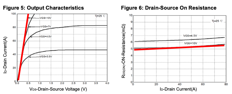
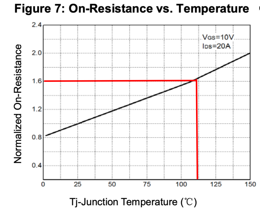
Let’s say the FET reaches (worst case) 110°C, we get $R_{dsOnMax} = 5m\Omega \times 1.6 = 8m\Omega$ Let’s say $10m\Omega$ to be conservative.
The copper pour is proportionally OK (gave it the most I could) but the board size is the limiting factor to dissipate all the heat.
So let’s determine a borad Thermal Resistance in $°C/W$.
First, the worst copper poor for a ft is going to be this one:
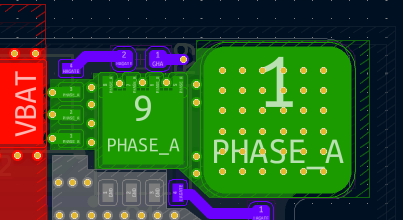
This top right mosfet has the smallest copper pour under its main thermal relief pas (and hence, the one limiting the design).
SUing kicad, I estimate a 180mm^2 copper pour including the exposed pad. It has 2 layer connected by enough vias to easily spread the current accross layers. And even though ther are not place under the pad, we can say current is going to be spread evenly to the second inner 180mm^2 copper pour on the inside of the board.
Also, because the copper pour is rather short, we’ll assume an isothermal setup.
We’ll lay down the total thermal resistance:
\[R_{thJA} = R_{thJC} + R_{via} + R_{spread} + R_{convection}\]$R_{thJC}$ is the drain pad to copper term. it can be ignored here as themral conduction is basically super high and neglectable.
\(R_{via}\) is the vias term, in parrallel , there are also pretty neglectable. Per via it is given at $192.414°C/W$ according to the RFTools.io clculator. I have 50 in parrallel on this pour. To be conservative as not every one of them are as close to the heat source (even though I said it was isothermal but who cares), let’s cut it to 30. This gives us $6.4138 °C/W$
$R_{spread}$ is ignored as we said the pour is isothermal at this size.
$R_{convection}$ is the actual number that scares me, as this is the actual resistance that takes into acount the transfer of enrgy from the copper to the air.
Here are my estimates for this taking my copper pour size:
these are rough as I do this in my free time and don’t wanna do the calculations lol
- In still air : $85 °C/W$
- With propwash : $25 °C/W$
Which means , whith an initial temperature of 25°C and T_max determined earlier to be 110°C, we have in still air:
\[P_{lossMax} \times R_{thJA} = (T_{max}-T{Ambiant})\] \[P_{lossMax} = (T_{max}-T{Ambiant}) \div R_{thJA} = 85 / 85 = 1W\]With an estimated dropped voltage when conducting of $U_{FetDropTypical} = 0.3V$:
\[P_{lossMax} = U_{FetDropTypical} \times I_{max} \implies I_{max} = 1W / 0.3V = 3.33Amps\]Which kinda sucks ass to be honest. But given a FET only condusts 1/3 of the time but still loses more during transient, we can eyeball a safe coefficient of 1.5x of allowable current (again, don’t wanna run aboslutly all the number, we’ll just stay conservative and it will be fine). Which gives use a theorical max in still air of $5A$.
Applying the same method for propwash scenario (i.e. wind ins blowing on the PCB, drastically imroving its thermal resistance by 2-3x fold), we get… $17A$.
okay this still kinda sucks ass. BUT to be honest this is a conservative shot at estimating such a number. Ideally we would want to run IRL tests but I don’t have the time so scew it, we’ll tell the firmware to not got to hard on the board for too long and everythin should be just fine :)
Side note, the 1.5x factor and the voltage drop are really conservative estimates, rerunning the numbers using P = I^2 x Ron we get way better results but let’s tay conservative !
Personnal thoughts on the project
Okay so everall the project was really great. I learned a gazillion thing that will be super useful for later and that I’m already usgin at my job, making me more engaged with my day to day job operation, which is super cool.
It was bit longer than I expected though but learning stuff takes time.
The thing that kinda got me down is the video, I really enjoyed editing it, made something I’m pretty pround of, got the sponsor etc… but turns out ESCs aren’t really exciting content nowdays. Even thoug I make youtube video for fun, the results can (most of the time) largely underperform expectations which kinda sucks. But that’s life !
BTW, sorry for the typos, I write fast and publish right after, I’ll fix some in the upcomming days ;)
Godspeed
-BRH